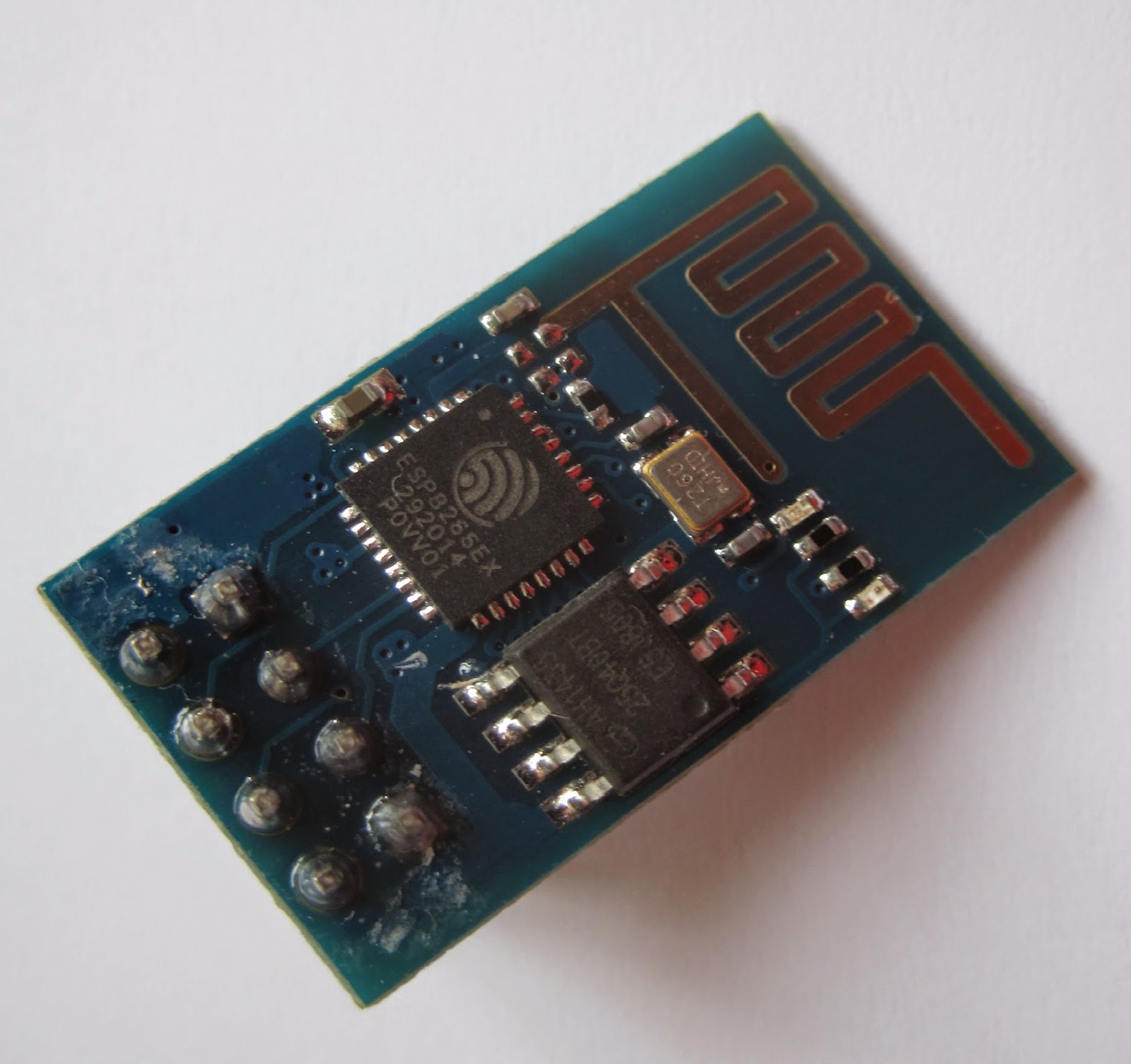
Part 1 - ESP8266 ESP-01
One of these arrived in the post a couple of days ago.In its basic form it is a serial to wifi converter, with built in network stack and aerial. Connect to the serial port and you can connect out through wifi. This is a simple solution to connect an existing project to a network over a serial connection.
What interested me was being able to write my own firmware, control the GPIO's and send data wirelessly. For simple projects an external processor should not be required, for example, report the temperature every hour and save to a webserver.
Programming with a Raspberry Pi
Connect ground of the power supply to ground of the ESP8266 and to the ground of the Raspberry Pi, 3.3v to Vcc, and tx & rx to a 3.3v serial connection. Most serial ports are 12v and that will fry the ESP-01.
I've used a Raspberry Pi B as the serial port is already at 3.3v so no level shifts are required. I've used a separate power supply as the B does not supply enough current to power the board directly,
The board comes with built in "AT" firmware. This is basically an extension of the Hayes modem commands allowing you to control the board over a serial connection.
The current firmware requires a CR+LF so ensure this is enabled on your terminal. You will not get a response otherwise.
Standard commands are AT, this should get back an OK from the device to say its working
AT
OK
Get the current firmware version AT+GMR
AT
00170901
OK
Writing Your Own Firmware
This is where it gets interested! There is plenty of guides how to install the development environment.
I started with the "basic_example"
#include "ets_sys.h"
#include "osapi.h"
#include "gpio.h"
#include "os_type.h"
#include "user_config.h"
#include "user_interface.h"
#define user_procTaskPrio 0
#define user_procTaskQueueLen 1
os_event_t user_procTaskQueue[user_procTaskQueueLen];
static void loop(os_event_t *events);
//Main code function
static void ICACHE_FLASH_ATTR
loop(os_event_t *events)
{
os_printf("Hello\n\r");
os_delay_us(10000);
system_os_post(user_procTaskPrio, 0, 0 );
}
//Init function
void ICACHE_FLASH_ATTR
user_init()
{
// Set baud rate of debug port
uart_div_modify(0,UART_CLK_FREQ / 115200);
//Start os task
system_os_task(loop, user_procTaskPrio,user_procTaskQueue, user_procTaskQueueLen);
system_os_post(user_procTaskPrio, 0, 0 );
}
The extra line
uart_div_modify(0,UART_CLK_FREQ / 115200);
sets the baud rate of the debug port, otherwise is defaults to 74880
After flashing I use piccom and this is the result:
Hello
Hello
Hello
Hello
Hello
Hello
Hello
Hello
Hello
Hello
Hello
Hello
Hello
Hello
Hello
Hello
Hello
Thanks for using picocom
pi@raspberrypi /opt/Espressif $
Next stage is to use WIFI (2. Connect to an Access Point)


No comments:
Post a Comment